Quantcast
Channel: Planet CNC
Viewing all 86 articles
Browse latest View live

List of essential PlanetCNC TNG tutorials

$
0
0

New to PlanetCNC TNG software? Don’t worry, here you can find list of tutorials that explain how to start using PlanetCNC TNG software as fastest and as effectively as possible.

It is very recommended to follow these tutorials in chronological order:

1. PlanetCNC TNG software overview and performance guidelines
Short description of PlanetCNC TNG software and few guidelines for better perfomance.

2. Updating to new PlanetCNC USB driver
PlanetCNC TNG software uses new digitaly signed PlanetCNC USB driver. See how to install it on you computer.

3. Updating PlanetCNC controller with PlanetCNC TNG software
To update your PlanetCNC controller with PlanetCNC TNG software you need to follow sequence of steps.

4. PlanetCNC TNG Linux installation guide
PlanetCNC TNG software works also with Linux OS. See how it is installed on Ubuntu MATE.

5. Obtaining and activating license for PlanetCNC controller with TNG software

The post List of essential PlanetCNC TNG tutorials appeared first on Planet CNC.


Basic PlanetCNC TNG connection settings

$
0
0

PlanetCNC TNG software recognises all PlanetCNC controllers that are connected to your PC trough USB or Network ports. You would need to select controller that will serve as primary controller.

Basic connection settings:

Lets start by going trough connection parameters in settings: File/Settings/Connection

Select the type of connection that you wish to use with your controller:
-USB
-Network(Only Mk3 controller)
-“Adapter IP” setting allows you to insert your network adapter IP address.

When you select type connection, you will notice that window with connected devices will add new controller(s) to the list(beside Simulation).
To select your primary controller you double click on it.

Now that your primary controller is selected you can observe its communication status.

Connection light colour description:

If you look closely at the bottom right corner of PlanetCNC TNG software you will notice that there is a round light.
This light can be lit in various colours and each colour indicates different connection state.

Green light indicates that controller is updated to correct firmware version and controller is activated meaning license is found by software.

Green light with X indicates that software does not find proper license for connected controller.

Orange light indicates that controllers firmware version is not correct. Update firmware of controller.

Gray light indicates no communication between controller and software. Click “Machine/Controller/Reconnect” and make sure that correct controller is set as Primary controller in settings.

Red light indicates that software is processing commands and is sending them to controller.

Communication status can also be indicated by observing on-board Link LED. If this LED is blinking in pattern of approximately 500ms, controller is communicating with software. When software is processing commands and is sending them to controller, this LED will be blinking even faster.

If Link LED is not blinking, this indicates communication has dropped.

The post Basic PlanetCNC TNG connection settings appeared first on Planet CNC.

How to set Steps Per Unit values in PlanetCNC TNG software

$
0
0

Steps per unit value (in further text SPU) defines how many step pulses controller needs to generate in order that axis moves for distance of one unit. Units can be in millimeters or in inches.

SPU value depends on few factors: stepper motor, stepper drivers micro-step configuration, lead screw pitch:

Motor
Stepper motors usually have 200 or 400 full steps per one rotation of its shaft.
One rotation of shaft in degrees is 360°. For motors with 200 steps per revolution this means
one step is equal to 1.8°. For motors with 400 steps per revolution this means one step is equal to 0.9°.

In equation below, we will name this parameter M

Micro-Stepping
With micro-stepping we improve motors resolution, accuracy, smoother movements, we reduce
resonance problems etc. The real compromise is that as you increase the number of micro-steps per
full step the incremental torque per micro-step drops off drastically. Resolution increases but
accuracy will actually suffer.

With micro-step number we define, how many smaller steps is one full step divided into.
Most common values are ½ , ¼ , ⅛… but it is really up to you which micro-step value you will use.

In equation below, we will name this parameter S

Pitch
Usually CNC machines operate with the help of lead screws and nuts. They can be trapezoidal or
ball screw leads. The pitch of a screw thread is the distance between adjacent threads. When lead
screw is rotated for one revolution, this reflects as linear motion of axis. Distance traveled is equal
to lead screw’s pitch.

In equation below, we will name this parameter P

(Some CNC machines use rack and pinion instead. Distance traveled when pinion makes one
revolution can also be considered as pinion pitch. Similar is also true for toothed belt drive.)

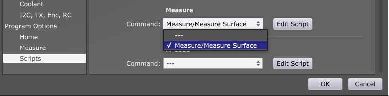
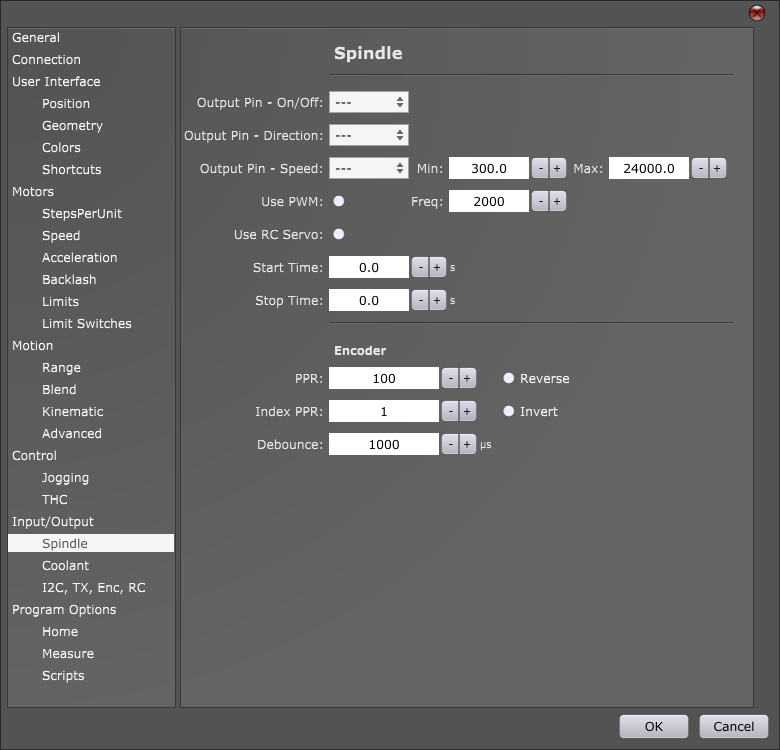
Setting SPU values of your machine in PlanetCNC TNG software

StepsPerUnit tab can be found in settings under Motors section: File/Settings/Motors
SettingsSPU

We can calculate SPU values for our machine by starting from two different conditions:

If we know all variable values:
Calculating correct SPU value is easy: SPU value = (M*S)/P

If we don’t know all variable values:
We will have to do some measuring and provide ourselves with some numbers. Then we will be able to calculate correct SPU value.

We use metric units so our unit is millimeter. If you use imperial units (inches) then values are different.

1) In Settings/Axes/Setup we set our SPU value to some “normal” number, say 200 steps per unit.

SettingsSPU200

2) Jog machine to a suitable location, and set: Machine/Work Position/Axis to Zero/XY offsetXY.

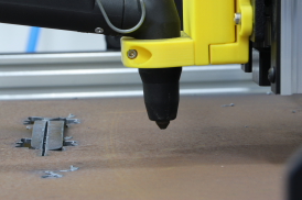
3) Now let’s say that we want to move X axis from our offset zero position to X=10 position and measure the actual distance for which machine will move. To measure the distance of machines travel, we can use ruler, caliper or measuring tape which we place under machines tool.

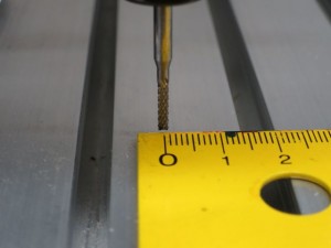
Tool should start at 0 of the ruler:
X0TNG

In MDI window write X10:
MDIx10

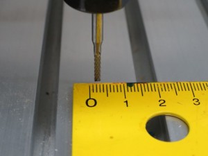
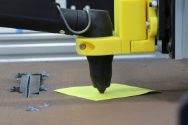
Machine should move from X=0 to X=10, therefore travel for 10mm, but when we execute MDI command we can see that machine travelled for 2.5mm instead of 10mm:
X3.5TNG

Meaning, our current SPU value moves machine axis for wrong distance.

4) We can ask ourselves a question:

If ‘Current SPU’ value moves X axis for ‘Measured distance’ value, what is the ‘Correct SPU’ value that will move X axis for ‘Entered distance’ value?

Equation looks like this:
Correct SPU value = ( Current SPU value * Entered distance value ) / Measured distance value

Current SPU = 200
Entered Distance = 10
Measured distance = 2.5

Correct SPU value= (200*10)/2,5 = 800 SPU

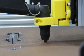
Now we enter correct value for SPU in Settings/Axes/Setup, Enter X10 in MDI window and measure the new distance value.
X0TNG

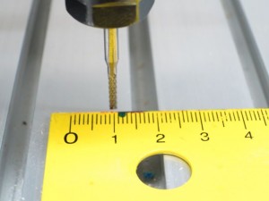
Measured distance value is now correct. Our steps per unit are correctly set.
X10TNG

It is recommended to repeat this procedure several times and use largest possible travel. Using 10mm travel is good for first pass but if you use maximum possible distance machine can travel, you will obtain much better results.

The post How to set Steps Per Unit values in PlanetCNC TNG software appeared first on Planet CNC.

How to set Motor limits in PlanetCNC TNG software

$
0
0

To set your axis motor limits click: File/Settings/Motors -> “Motor Limits”.
MotorLimitsTab

Limit- value sets limitation of motor movement in negative direction, Limit+ value sets limitation of motor movement in positive direction:

MotorLimitsTabValues

To enable Motor limits for specified axis click the round button:

MotorLimitsEnabled

The post How to set Motor limits in PlanetCNC TNG software appeared first on Planet CNC.

How to set Motion Limits in PlanetCNC TNG software

$
0
0

To set motion limits of your machine click: File/Settings/Motion-> “Motion Limits”

Motion Limits tab

Limit- value sets limitation of machine/effector (tool) movement in negative direction, Limit+ value sets limitation of machine/effector (tool) movement in positive direction for specific axis:

MotionLimitsValues

With Motion limits values inserted, we set motion limits of machine. If we want machine to stop when limits are reached we must enable them.
To enable Motion limits for specified axis click the round button:

MotionLimitsValuesEnabled

When you set your machines motion limits you will notice that 3D representation of machine limits will be displayed accordingly on the main screen:

3DDisplayValues

If you use normal XYZ axis machine then we recommend that you set your motion limits at same values as motor limits.

You are probably wondering what is the difference between Motor limits and Motion limits?
We try to think that motor limits are limiting actual motor movement and Motion limits are limiting machine or effector (tool) movement.

Eleboration:
With use of combined motors and special mechanics you can achieve movement which doesn’t follow the same kinematic rules as linear motion CNC’s.
Examples of such machines are H-bot, Delta printer or multiple axis machines. In such cases values for Motor limits and Motion limits would not be the same.

The post How to set Motion Limits in PlanetCNC TNG software appeared first on Planet CNC.

How to set Homing procedure in PlanetCNC TNG software

$
0
0

Homing procedure will reference your machine and set machine work area.

1. First you need to configure these settings:
Motor limits(File/Settings/Motors/Limits):
Set limitation of movement for each motor.
Motor limits tutorial can be found on this link: Motor Limits tutorial

Limit switch input configuration(File/Settings/Limit/Limit Switches):
Configure limit switch inputs of controller.

Switch hysteresis(File/Settings/Limit/Switch Hysteresis):
Distance which machine needs to travel in order that activated switch is released.

Limit switch input configuration and switch hysteresis tutorial can be found on this link: Limit switch input configuration and switch hysteresis tutorial

Home speed(File/Settings/Program Options/Home Speed):
Set homing speed.

Home position(File/Settings/Program Options/Home Position):
This is the position where machine will return after homing is complete.

2. To execute homing procedure click: Machine/Home or click the “Home” button located on vertical toolbar: HomingButton

When Homing is executed, default homing sequence will be:

Z axis will homed first. Axis will move in positive direction until Z axis limit switch is activated. When switch is activated machine stops and moves back just enough to release limit switch.

X axis will homed second. Axis will move in negative direction until X axis limit switch is activated. When switch is activated machine stops and moves back just enough to release limit switch.

Y axis will homed third. Axis will move in positive direction until Y axis limit switch is activated. When switch is activated machine stops and moves back just enough to release limit switch.

3. If you would like to change order of homing sequence movements, direction or speed of homing you can do that by editing the homing script file.

When you click home button for the first time, Machine.Home.gcode default file will be created. Open your PlanetCNC TNG software installation folder and locate folder: “.Scripts”

Find “Machine.Home.gcode” file and open it with text editor:

DefaultCode

Let say that we would like to change the direction and order of homing sequence movements. We want X axis to be homed first and in positive direction. Y axis homed second in positive direction, and we will leave homing for Z axis as it is.

The modified homing g-code would now look like this:

ModifiedCode

4. Description of parameters:

<_motorlimit_xp>: Limit value of Motor Limit+ parameter for Motor X. Set in settings.
<_motorlimit_xm>: Limit value of Motor Limit- parameter for Motor X. Set in settings.

<_motorlimit_yp>: Limit value of Motor Limit+ parameter for Motor Y. Set in settings.
<_motorlimit_ym>: Limit value of Motor Limit- parameter for Motor Y. Set in settings.

<_motorlimit_zp>: Limit value of Motor Limit+ parameter for Motor Z. Set in settings.
<_motorlimit_zm>: Limit value of Motor Limit- parameter for Motor Z. Set in settings.

<_refswitch_hysteresis>: Limit switch hysteresis value. Set in settings.

<_speed_home>: Homing speed value. This value can be set directly with new F value. In such case you should delete the “#<_speed_home>” line of code.

5. Description of homing script g-codes:

M73:
This g-code saves states of of all modal g-codes currently used by software. When Machine.Home.gcode procedure is executed in its entirety and , all states will be restored to their
previous values.

G90:
this g-code sets absolute mode of motion.

G38.1:
This g-code moves selected axis in selected direction.
G38.1 g-code uses parameter X(-/+)Value,Y(-/+)Value or Z(-/+)Value which define to which coordinate value machine should move and in what direction.
When limit swith activation occures over the time of machine travel, machine will stop.

G10 L9:
When G38.1 g-code senses and stops the machine, this g-code sets current absolute position for selected axis .
Example:
G10 L9 Z[#<_motorlimit_zp> + #<_refswitch_hysteresis>]: Absolute position Z will now be the value of motor limit (Z+) + switch hysteresis value.

G53 G0: Machine moves in absolute coordinates.
Example: If new machine absolute position is the one saved with G10 L9 g-code((Z+) + switch hysteresis value), we move machine back to Motor limit+, thus releasing activated limit switch for value of its hysteresis.

Homing procedure can be configured to fit yor needs. You can set homing speed, axes homing order, home position etc…

The post How to set Homing procedure in PlanetCNC TNG software appeared first on Planet CNC.

How to configure limit switch inputs of controller in PlanetCNC TNG software

$
0
0

Limit switches are used to reference your machine(homing procedure) as also for safety reasons.

If you use only one limit switch for axis X motor (positive direction), connected to controllers limit input 1:

XAxis+

If you have two limit switches for axis X motor (negative and positive direction), connected to same limit input of controller:

XAxis+-

If you have two limit switches on X axis(negative and positive direction), connected to separate limit inputs of controller:

XAxisSeparatePin

Switch hysteresis:
This is the distance from the moment when limit switch is activated to when limit switch is released. Usually around 2-5mm. Test this on your machine.

Same principles that were shown above for X axis can be used for all other axes.

Limit switch test:

When your limit switches are connected to limit inputs of controller, you can test if PlanetCNC TNG software senses the limit switch activation. On main screen click the “IO” tab and observe controllers Limit status bar behaviour:

Limit1_IO

Limit1_IO_Active

Invert option:
If you use normally closed type of limit switches then you can invert controller limit input in settings: File/Settings/Limit

LimitInvert

Click round button next to limit pin that you wish to invert:

LimitInvertEnabled

The post How to configure limit switch inputs of controller in PlanetCNC TNG software appeared first on Planet CNC.

How to measure tool offset using fixed tool sensor in PlanetCNC TNG software

$
0
0

1. Reference your machine using Homing procedure(Machine/Home):
How to set Homing procedure in PlanetCNC TNG software

2. Mount your fixed tool sensor(further in text referenced as sensor) on machine table.

3. Connect sensor to one of the inputs (Input connector) of controller.
InputWiringMk34

InputWiringMk3

4. In settings select either Sensor 1 or Sensor 2(File/Settings/Input/Sensors). It doesn’t matter which one you choose.

From drop down menu select input to which you connected your sensor.

SensorInput1

5. Activate sensor by hand and under IO tab of main display check if designated input gets properly triggered.
SensorInput1_IO

For safety reasons jog your machine (it can be in any direction) and see if machine stops when you activate sensor.

6. Jog your machine to sensor position, so that tool is right above the centre of fixed tool sensor.
For Sensor Position(File/Settings/Program Options/Sensor Position)insert X,Y motor values that can be seen under Motors tab of coordinate display.
Z value of sensor position is usually sensors height. Sensor Position(File/Settings/Program Options/Sensor Position).

7. Start Measure Tool procedure(Machine/Tool Offset/Measure Tool).
You can also use the “Tool Offset Measure Tool” button on the left toolbar:
ToolbarButton

8. When “Measure Tool” procedure is executed, default tool measure sequence will be:

Machine will ascend to safe height and move from current position to sensors XY position(the one we set in settings).

Machine will descend towards sensor with probe speed(File/Settings/Program Options/Probe Speed) and when sensor gets activated, machine will stop and ascend to safe height.
Machine will return back to XY position from which we started the “Measure Tool” procedure.

You have configured your fixed tool sensor and you should be able to use “Measure Tool” procedure.

If you would like to edit “Measure Tool” procedure to fit your needs or to have more in depth look at the tool measure procedure itself, you can do that by opening the tool measure script file.


9. You can create and access “Measure Tool” procedure script file  in two ways:

a.) In settings (File/Settings/Program Options/Scripts/Tool Offset) you can click buttons Generate and Edit. With Generate button you create default file and with Edit button you can open it and make any modifications of the script g-code

GenerateEdit

b.) When you start “Measure Tool” procedure for the first time, Machine.Tool_Offset.Measure_Tool.gcode default file will be created. Open your PlanetCNC TNG software installation folder and locate folder: “.Scripts”

Find “Machine.Tool_Offset.Measure_Tool.gcode” file and open it with text editor:

MeasureScript


10. Description of parameters and g-codes(in order of appearance in script g-code):

M73:
This g-code saves states of of all modal g-codes currently used by software. When Machine.Tool_Offset.Measure_Tool.gcode procedure is executed in its entirety, all states will be restored to their previous values.

#1 = # (store current x position): Stores value of current X axis position as parameter #1.
#2 = # (store current y position): Stores value of current Y axis position as parameter #2.
#3 = # (store current z position): Stores value of current Z axis position as parameter #3.

G90:
With G90 g-code we set absolute mode of motion. Prior to “Measure Tool” procedure , motion mode could be different so we used M73 to save current modal states.

G53 G0 Z#<_motorlimit_zp>:
Machine ascends to safe height.

G53 G0 X#<_sensor_x> Y#<_sensor_y>:
Machine moves to sensor XY position.

F#<_speed_probe>:
Speed at which machine descends to measure tool. Set with Probe Speed in settings(File/Settings/Program Options/Probe Speed). This value can be set directly with new F value. In such case you should delete the “#<_speed_probe>” line of code.

G38.2 Z-100000:
This g-code moves selected axis in selected direction. G38.2 g-code uses parameter X(-/+)Value,Y(-/+)Value or Z(-/+)Value which define to which coordinate value machine should move and in what direction. When probe activation occurs over the time of machine travel, machine will stop.

G43.1 Z[#<_probe_z> – #<_sensor_z>]:
When G38.2 g-code senses that sensor is activated and stops the machine, this g-code sets tool offset.

G53 G0 Z#<_motorlimit_zp>:
Machine moves in absolute coordinates to safe height.

G0 X#1 Y#2:
Rapid move to position from which we started the “Measure Tool” procedure .

o<100> if[[TOABSZ[#3] LT #<_motorlimit_zp>] AND [TOABSZ[#3] GT #<_motorlimit_zm>]]
G0 Z#3 (move to last z position)
o<100> endif

With this sub program we make sure that we are safely within Z axis motors limits when machine moves back to position from which we started the “Measure Tool” procedure .

The post How to measure tool offset using fixed tool sensor in PlanetCNC TNG software appeared first on Planet CNC.


How to measure work position with movable sensor in PlanetCNC TNG software

$
0
0

1. Reference your machine using Homing procedure(Machine/Home):
How to set Homing procedure in PlanetCNC TNG software

2. Connect movable sensor (further in text referenced as sensor) to one of the inputs (Input connector) of controller.

InputWiringMk34

InputWiringMk3

3. In settings select either Sensor 1 or Sensor 2 (File/Settings/Input/Sensors). It doesn’t matter which one you choose.

From drop down menu select input to which you connected your sensor.

SensorInput2

4. Activate sensor by hand and under IO tab of main display check if designated input gets properly triggered.

SensorIO

For safety reasons jog your machine (it can be in any direction) and see if machine stops when you activate sensor.

5. In settings set:

Probe speed(File/Settings/Program Options/Probe speed): This is the speed at which Z axis will descend to measure Z axis work position.

Sensor Thickness(File/Settings/Program Options/Probe speed): If you use copper board as a movable sensor, then value of this parameter is the thickness of the copper board( usually 1.6mm).

Thickness

 6. Start “Work Position Measure” procedure(Machine/Work Position/Measure). You can also use the “Work Position Measure” button on the left toolbar:

Button

7. When “Work Position Measure” procedure is executed, default sequence will be:

Machine will at current machine position descend towards sensor at probe speed(File/Settings/Program Options/Probe Speed). When sensor is activated, machine will stop and ascend to Z height from which we started “Work Position Measure” procedure.

Z axis work position value on surface of material should now be 0.

You have configured “Work Position Measure” procedure and you should be able to use it with your movable sensor.

If you would like to edit “Work Position Measure” procedure to fit your needs or to have more in depth look at the procedure itself, you can do that by opening the “Work Position Measure” procedure script file.


8. You can create and access “Work Position Measure” script file  in two ways:

a.) In settings (File/Settings/Program Options/Scripts/Work position) you can click buttons Generate and Edit. With Generate button you create default file and with Edit button you can open it and make any modifications of the script g-code

GenerateEdit


b.) When you start “Work Position Measure” procedure for the first time(for example via button), Machine.Work_Position.Measure.gcode default file will be created. Open your PlanetCNC TNG software installation folder and locate folder: “.Scripts”

Find “Machine.Work_Position.Measure.gcode” file and open it with text editor:

ScriptG-code

9. Description of parameters and g-codes(in order of appearance in script g-code):

M73:
This g-code saves states of of all modal g-codes currently used by software. When Machine.Work_Position.Measure.gcode procedure is executed in its entirety, all states will be restored to their previous values.

#3 = #<_abs_z>: Stores value of current Z axis position as parameter #3.

G90:
With G90 g-code we set absolute mode of motion.


F#<_speed_probe>:
Speed at which machine descends to measure tool. Set with Probe Speed in settings(File/Settings/Program Options/Probe Speed). This value can be set directly with new F value. In such case you should delete the “#<_speed_probe>” line of code.

G38.2 Z-100000:
This g-code moves selected axis in selected direction. G38.2 g-code uses parameter X(-/+)Value,Y(-/+)Value or Z(-/+)Value which define to which coordinate value machine should move and in what direction. When probe activation occurs over the time of machine travel, machine will stop.

G92 Z#<_sensor_thick>:

When movable sensor is activated, we set current work position as thickness of sensor. Here comes in great help g-code G92.

G53 G0 Z#3:

Machine moves in absolute coordinates to previously saved Z axis position.


The post How to measure work position with movable sensor in PlanetCNC TNG software appeared first on Planet CNC.

Controlling the Spindle and Coolant with PlanetCNC TNG Software

$
0
0

A fundamental operation in CNC machining is controlling the spindle. It is controlled in g-code using M3, M4 and M5 commands.
M03 will start the spindle turning clockwise.
M04 will start the spindle turning counterclockwise.
Both commands turn on the spindle at the speed determined separately by the S-word. It is used to set the RPM at which the spindle will turn when turned on.
M05 will stop the spindle regardless of direction.

Other than controlling the spindle, the M03 command can also turn on a plasma cutter, laser, water jet or even a hot wire for cutting polystyrene foam. Their power is likewise set using the S-word.

When machining some materials, most often metals, it is sometimes required to use coolant. It can be supplied to the tool and on the work in different ways. There are three commands for coolant control.
M07 will turn on the mist coolant supply.
M08 will turn on the flood coolant supply.
M09 will turn both coolant supplies off.

As with M03, these commands can be used to control something else, as they just turn an output on the CNC USB controller on or off. For example one of the codes could be used to control the dust collection vacuum for a woodworking machine.

The M07, M08 and M03 commands can also be activated manually using the buttons from top toolbar:
CoolantFlood CoolantMist SpindleM3


Currently active M-codes will also show up in the machine state display.

M03M07M08M05M09

The post Controlling the Spindle and Coolant with PlanetCNC TNG Software appeared first on Planet CNC.

Using G02 and G03 g-codes with PlanetCNC TNG software

$
0
0

Another two g-codes used to specify machine movements are G02 and G03. They move the machine in an arc, in contrast to G00 and G01 which move the machine in a straight line.

G02 moves the machine in a clockwise arc and G03 moves the machine in a counterclockwise arc.
To use these codes we need to specify the coordinates to which the machine will travel, the offsets to the center of the arc or the arc radius and optionally the number of additional turns the machine will make while performing the move. The speed of these movements is also defined by the F-word (feed rate).

For example: Starting from X0 Y0 Z0, we would like to round a 90 degree corner using a counterclockwise arc to X50 Y50 Z0. To do this we will use the command G03 X50 Y50. But this command isn’t complete yet and the program would signal an error if we tried to use it like that. We still need to specify the center of the arc. This is done by specifying offsets from the starting position or with the deprecated method of specifying the radius.

The offsets are simply the distance from the starting position to the center of the arc. The offsets are separated into components for each axis. The center also needs to be equidistant from both the starting and the destination point. Otherwise the arc won’t be part of a circle and the controller will signal an error accordingly.

As we said, the offsets are the distance the machine would need to move along each axis separately to get to the destination. In our case (starting from the origin) this would be 50 units along X and 50 units along the Y axis. This also means that the radius of the circle will be 50 units. Now we need to specify the offsets to the machine. To do this we use I, J and K-words for the X, Y and Z axes accordingly. When we put all this together we get the final code that looks like this: G03 X50 Y50 J50.

G03

The post Using G02 and G03 g-codes with PlanetCNC TNG software appeared first on Planet CNC.

Using the G04 g-code with PlanetCNC TNG software

$
0
0

In machining it is sometimes necessary to stop the motion of all axes for a given amount of time (for example to let the spindle come up to speed or wait for the coolant to start flowing). This is called dwell. It’s activated with the G04 command. The time is specified using a P-word and a number seconds (the number is a float so fractions of a second can be used).
For example: G04 P3.7

A common place to use the G04 dwell command is when starting a spindle of a machine. Because it can’t accelerate instantly to the desired speed we need to allow it some time to speed up before starting to cut the material. An example of code that waits 5 seconds after starting the spindle at 10000 RPM is here:
M03 S10000
G04 P5

The post Using the G04 g-code with PlanetCNC TNG software appeared first on Planet CNC.

How to create custom tabs in PlanetCNC TNG software

$
0
0

With PlanetCNC TNG user can create his own custom tabs.

Tabs are displayed on main user interface and can include any parameter used by software whether its tool offset value, number of g-code line or absolute position of machine. By default, software will display tabs “Speed” and “IO”.

User can create maximum of  5 state files, meaning, you can display up to 5 custom tabs. File with extension .state1 creates first tab file, .state2 creates second tab file all the way up to .state5 file.

To create new custom tab go to your PlanetCNC TNG installation folder and create new text file and change its name to PlanetCNC64 or PlanetCNC32 and its extension to “state1“: PlanetCNC64.state1 or PlanetCNC32.state1

It is worth mentioning that the text before .state must be the same as name of your settings file. So, if your settings file is named: MyCNCRouter.settings, then your corresponding .state file should be named MyCNCRouter.state1. This way you can link multiple state files to corresponding setting files.

Now open this file and copy/paste bottom example text for an easy start:

If we look parameter “_abs_x 3” you can see that at the end we add number 3. Since this parameter is X axis absolute position value, this number means number of decimal places.

If parameter uses Boolean logic you add instead of number a letter B.

Now that we created  state file and we configured it, “My new tab” tab should appear after we restart PlanetCNC TNG software:

If we click “My new tab” tab we can see the parameters displayed:

Parameter 1 displays X axis absolute position
Parameter 2 displays Total run time of g-code file
Parameter 3 displays SPU value of X axis

We can change names of parameters to make them more understandable:

Now parameter names are much easier to understand:

You can download state file with all parameters here: All parameter .state file

The post How to create custom tabs in PlanetCNC TNG software appeared first on Planet CNC.

How to control PlanetCNC TNG from your own software

$
0
0

Command line arguments

PlanetCNC TNG accepts commands from command line. Only one software instance can run at same time. When you run second instance it will simply pass its arguments to running instance. Running instance will process these arguments and execute command.

Here are some examples (Windows, 64bit):

1. Open command prompt.
2. Go to PlanetCNC TNG installation folder. Usually “C:Program Files (x86)PlanetCNC”.
3. Type PlanetCNC64.exe. Software will start.
4. Type PlanetCNC64.exe gcode “G01 X10G01 Y10”. You will notice that two g-code lines are now loaded.
5. Type PlanetCNC64.exe start. Machine will start and g-code will be executed.

Named pipes

More advanced option is to use named pipes. Named pipes is simple cross-platform interprocess communication mechanism. It is possible to use named pipes in almost all programming languages.

PlanetCNC TNG must be running otherwise it will not receive command. If you do not want to show main window you can start software with “hide” command.

Here is source code of an example (Windows, C++):
PipeExample


List of supported commands

Both options described above use same commands. Here is a list and brief explanation.

show Shows main window
hide Hides main window
exit Exits program
estop Toggles EStop
start Performs Start
stop Performs Stop
pause Performs Pause
isestop Returns 1 if EStop is active, 0 otherwise
ispause Returns 1 if Pause is active, 0 otherwise
open "filename" Opens GCode from file
gcode "program" Opens GCode from string
close Closes opened GCode
mdi "command" Executes MDI command
param name=value Sets parameter value
param name Returns parameter value
posabs Returns absolute position for all axes
posabsx Returns absolute position for X axis
posabsy Returns absolute position for Y axis
posabsz Returns absolute position for Z axis
posabsa Returns absolute position for A axis
posabsb Returns absolute position for B axis
posabsc Returns absolute position for C axis
posabsu Returns absolute position for U axis
posabsv Returns absolute position for V axis
posabsw Returns absolute position for W axis
pos Returns position for all axes
posx Returns position for X axis
posy Returns position for Y axis
posz Returns position for Z axis
posa Returns position for A axis
posb Returns position for B axis
posc Returns position for C axis
posu Returns position for U axis
posv Returns position for V axis
posw Returns position for W axis
speed Returns current speed
accel Returns current acceleration
spindle Returns current spindle RPM
input Returns value of INPUT
input1 Returns value of INPUT 1 pin
input2 Returns value of INPUT 2 pin
input3 Returns value of INPUT 3 pin
input4 Returns value of INPUT 4 pin
input5 Returns value of INPUT 5 pin
input6 Returns value of INPUT 6 pin
input7 Returns value of INPUT 7 pin
input8 Returns value of INPUT 8 pin
jog Returns value of JOG
jog1 Returns value of JOG 1 pin
jog2 Returns value of JOG 2 pin
jog3 Returns value of JOG 3 pin
jog4 Returns value of JOG 4 pin
jog5 Returns value of JOG 5 pin
jog6 Returns value of JOG 6 pin
jog7 Returns value of JOG 7 pin
jog8 Returns value of JOG 8 pin
joga1 Returns value of JOG A1 pin
joga2 Returns value of JOG A2 pin
jogs Returns value of JOG S pin
jogpot Returns value of JOG POT
limit Returns value of LIMIT
limit1 Returns value of LIMIT 1 pin
limit2 Returns value of LIMIT 2 pin
limit3 Returns value of LIMIT 3 pin
limit4 Returns value of LIMIT 4 pin
limit5 Returns value of LIMIT 5 pin
limit6 Returns value of LIMIT 6 pin
limit7 Returns value of LIMIT 7 pin
limit8 Returns value of LIMIT 8 pin
limit9 Returns value of LIMIT 9 pin
output Returns value of OUTPUT
output1 Returns value of OUTPUT 1 pin
output2 Returns value of OUTPUT 2 pin
output3 Returns value of OUTPUT 3 pin
output4 Returns value of OUTPUT 4 pin
output5 Returns value of OUTPUT 5 pin
output6 Returns value of OUTPUT 6 pin
output7 Returns value of OUTPUT 7 pin
output8 Returns value of OUTPUT 8 pin
aux1 Returns value of AUX 1 pin
aux2 Returns value of AUX 2 pin
aux3 Returns value of AUX 3 pin
aux4 Returns value of AUX 4 pin
buffer Returns amount of free buffer
bufferpercent Returns percent of buffer utilization
linecount Returns number of lines in GCode program
line Returns line number currently executing


Starting program from g-code

You can also start your own program from gcode. Optionally you can wait for program to finish before g-code continues or you can pass parameters.

Start myprogram.exe:
(exec,myprogram.exe) 

Start myprogram.exe and send current X and Y coordinates:
(exec,myprogram.exe #<_x> #<_y>) 

Start myprogram.exe, send current X and Y coordinates and wait for program to finish:
(execwait,myprogram.exe #<_x> #<_y>) 

Make sure that myprogram.exe is added to whitelist in settings otherwise TNG will refuse to execute it.

Hint: This external program can use named pipes to set some g-code parameters. TNG will use these parameters when g-code execution will continue.

The post How to control PlanetCNC TNG from your own software appeared first on Planet CNC.

How to create “Spindle Delay” script file in PlanetCNC TNG software

$
0
0

With PlanetCNC TNG software user can create or customise g-code procedures (e.g. for M3/M5 g-codes, M6 g-code) using script files.

Script files are located in PlanetCNC TNG installation folder in scripts folder.

If your settings file is named e.g.”MyCNCRouter.settings”, then your corresponding scripts folder should be named MyCNCRouter.scripts. This way you can link multiple script files to corresponding setting files.

To add short delay after spindle is turned ON,  we add G04 g-code after M3 g-code line.

To create and modify M3 g-code script please follow steps below.

1. Open PlanetCNC TNG software installation folder. Locate scripts folder and open it.

2. Create new text file and name it: Machine.UserDefined_M3.gcode

3. Open script file with text editor.

4. Add M3 and M04 g-codes.

Scipt file includes g-code lines:

M3
G04 P5

Now after each time we turn spindle ON, software waits 5 seconds before it continues with program execution.


You can read more on M3 and G04 g-codes here:
https://planet-cnc.com/controlling-spindle-coolant-planetcnc-tng-software/
https://planet-cnc.com/using-g04-g-code-planetcnc-tng-software/

The post How to create “Spindle Delay” script file in PlanetCNC TNG software appeared first on Planet CNC.


Using “Warp” with PlanetCNC TNG software

$
0
0

Since PCB milling is a very delicate and precise procedure (distance between two pads can be only few mils), already smallest PCB surface height irregularities can create bad results.

So it is very important that depth of milling is constant over the whole PCB surface throughout the whole milling process. We can achieve this by using “Warp” procedure.

‘Warp’ feature helps apply generated toolpath over bended, curved or uneven surfaces.

The most important step of ‘Warp’ procedure obtaining surface points. We can  either capture each point single-handedly  or we can use “Measure Surface” procedure. We recommend the latter.

Step 1:
Place your workpiece material (in future text ‘copper board’) to machines table. Mount it properly, so that you avoid any inconveniences later such as vibration, dislocation etc…also make sure that copper board is not in contact with the machine table.

Step 2:

Since copper board itself is conductive material,  it can already be used as sensor. You can solder wire to it or you could just use mounting screw to attach connection wire to copper board.

Now connect wire from your copper board to controllers ‘sensor’ input.

Other wire should be connected to controllers GND terminal. Other end of this wire can be clamped to engraving tool:

While Mk3/4 controller has a designated sensor input, Mk3 controller uses assignable inputs, so you can connect copper board wire at any input of Input header and configure it in settings later.


Step 3:

Now open IO tab and check if correct input is activated under “Input” panel. This is just to be sure that everything is working correctly. Image below shows that Input 1 is activated.

Step 4:

Jog your machine to desired initial origin point of your copper board, usually its corner, and click: “Machine/Work Position/Axis to Zero/XY” or click “Work Position Axis to Zero XY” button from toolbar.

With work position XY set to zero, you have initial point of your workpiece material from which you will start your ‘Warp’ measuring as also your g-code program.

Step 5:

To measure Z axis zero work position, click: “Machine/Work Position/Measure”  or click “Work Position Measure” button from toolbar.


Step 6:

Now that we set zero XY and Z axis work positions, we can start with surface point measuring.

Click “Machine/Measure/Measure Surface”:

“Measure surface” user dialogue will appear:

Position X: X axis initial point of surface measuring.

Position Y: Y axis initial point of  surface measuring.

Size X: X axis dimension of measuring area surface.

Size Y: Y axis dimension of measuring area surface.

Step: Distance between to neighbourly measuring points 


Step 7:

After you click OK, machine will begin measuring surface points of copper board.


Step 8:

When surface measuring procedure is finished,  measured points are saved in PlanetCNC TNG main installation folder as “MeasureSurface.txt” file.

Step 9:

Now open your Gerber file using “File/Import Gerber”:


Step 10:

Set Z axis work position to zero, click: “Machine/Work Position/Measure”  or click “Work Position Measure” button from toolbar.

Step 11:

To apply “Warp” click: “Program/Warp” and click “Load…” button. Locate file “MeasureSurface.txt” and click Open.

Table will be populated with coordinates of measured points:

Click OK.


Step 12:

You will notice that the displayed toolpath has changed in order to compensate for boards curved surface. This is much more evident if you set parameter “Alpha” in settings(File/Settings/User Interface/Colors/Alpha).

These are all steps required to apply Warp with your program. Machine will mill at constant depth no matter of the surface curvature.


PLEASE NOTE:

“Measure surface” script file is available for edit.

You can open and edit script file if you click: “File/Settings/Program Options/Scripts/Measure” and select “Measure/Measure Surface” from drop down menu. Click: “Edit Script” and script file will open in your default text editor.

Alternatively you can open surface measure script file “Machine.Measure.Measure_Surface.gcode” located in “PlanetCNC64.Scripts” folder with your text editor.


The post Using “Warp” with PlanetCNC TNG software appeared first on Planet CNC.

Adding user toolbar buttons in PlanetCNC TNG software

$
0
0

PlanetCNC TNG software offers option of creating and adding custom buttons to software toolbars.

Buttons can be added to top, bottom, left sided and right sided toolbars.

Custom buttons can execute any feature from File, View, Program, Machine and Help menu.

For this tutorial we will create and add buttons to top toolbar of PlanetCNC TNG software for features: Settings (File/Settings) and Log dialogue (Help/Log)


Step 1.:

Create new text file and name it: PlanetCNC64.btntop

File should be located in PlanetCNC TNG install root folder.

Modifying this file, you create custom buttons located at top toolbar.

Please note: “PlanetCNC64” is name of settings used, if your settings are named differently then this file should have different name.


Step 2.:

Open file PlanetCNC64.btntop with your text editor.

Step 2.1.:

To create button for “Settings” insert this line:

File.Settings_… SET

Open File menu and locate Settings feature:

If you look closely at the text of inserted line you can see that it is actually path to location of this feature, with difference that level is replaced with “.” and spaces are replaced with “_”.

To name the newly created custom button, you add desired text at the end of the line(SET). Make sure that one space is added  before you type the name of the button.


Step 2.2.:

To create button for “Show Log” insert this line:

Help.Show_Log_… LOG

Open Help menu and locate Show Log feature:

If you look closely at the text of inserted line you can see that it is actually path to location of this feature, with difference that symbol level is replaced with “.” and spaces are replaced with “_”.

To name the newly created custom button, you add desired text at the end of the line(LOG). Make sure that one space is added  before you type the name of the button.

Step3:
Buttons will appear on top tool bar after you restart PlanetCNC TNG software:


To create a divider line between the buttons you just add three hyphen ( – – – ) between the text lines:

File.Settings_… SET
– – –
Help.Show_Log_… LOG


To add buttons on left, right, top and bottom toolbars create these files and use same procedure as above:

PlanetCNC64.btnbottom: With this file you create custom buttons located at bottom toolbar

PlanetCNC64.btnleft: With this file you create custom buttons located at left sided toolbar

PlanetCNC64.btnright: With this file you create custom buttons located at right sided toolbar

Attached are files for custom buttons for top and left toolbars:
Custom button examples for TOP toolbar
Custom button examples for LEFT toolbar

Please remove .txt file extensions and replace them with btntop and btnleft. Also remove _2 in the name of the file for TOP toolbar.

The post Adding user toolbar buttons in PlanetCNC TNG software appeared first on Planet CNC.

Guidelines when submitting your problem to PlanetCNC support

$
0
0

Some users face an obstacle during their time learning and using PlanetCNC software.
While we always try to give fast and effective support, sometimes we need more info about the problem user is facing in order to come up with solution as fast as possible.

So when you post e-mail or ticket regarding your problem we ask you to provide the following:

1. Clear and in-depth description of your problem.
Please use English language if possible. Please understand that you know your machine and we don’t.

2. Attach files:
.settings(File/Export Settings)
.gcode (.dxf, .gerber)
.Scripts folder (zipped)
.var(located in your installation folder)
log text (Menu Help/Show Log then copy/paste)
.tbl(located in your installation folder)
.keys(located in your installation folder)
.state(State 1-5)
.btn(.btnbottom, .btnleft, .btnright, .btntop)
.script

3. Past experience has shown that video recordings can be very helpful.
Sometimes things do not go smoothly and error occurs during machine operation. In such case it is best to post two video files:

a.) Video of your machine during operation. Video should show machine operation and the exact moment when it comes to an error.
b.) Video of complete PlanetCNC sw user interface during the machine operation mentioned in point a.

This way we can compare both videos and see if anything unusual is happening in software and how software behaviour reflects on machine performance.
It is necessary that for this you use program and settings files that you sent us.

4. If any error message is displayed in PlanetCNC sw please make screenshot of it and post it.

These of course do not apply to each possible scenario, but you should be able to recognise what is applicable in your case.

The post Guidelines when submitting your problem to PlanetCNC support appeared first on Planet CNC.

Spindle synchronisation with PlanetCNC TNG

$
0
0

CNC lathe thread cutting requires spindle RPM’s to be synchronised with machines linear movement, we call this spindle synchronisation.

To achieve this, controller needs to read feedback signal from machines spindle to obtain information at which RPM spindle rotates.

For this purpose we can use incremental (with quadrature A and B signals ) encoder or some sort of sensor that would read spindle RPM’s.

If we would use only sensor, we could use optical or magnetic sensor.

But since encoders already use index signal, choosing encoder would satisfy all our needs.

Encoder should rotate at same rotational speed as spindle. Normally it is mounted directly on spindle shaft or connected to spindle shaft via pullyes and timing belt. In such case make sure that transmission rate is at 1:1.

Encoder uses two quadrature signals, A and B and  Index signal. For our purposes 100PPR(parts per revolution) encoder would do just fine.

Encoder is connected to controller via its CTRL header:


Encoder wiring  for Mk3 controller:

Signal A from encoder is connected to EN4A  pin and signal B from encoder to EN4B pin of CTRL header.

Index signal from encoder is connected to IDX pin of CTRL header.


Encoder wiring for Mk3/4:

Signal A from encoder is connected to ENC A  pin and signal B from encoder to ENC B pin of CTRL screw type terminal.

Index signal from encoder is connected to IDX pin of CTRL screw type terminal.

PlanetCNC TNG encoder settings:

Encoder settings are located in: File/Settings/Input/Output/Spindle -> Encoder

PPR: PPR value of your encoder.

Index PPR: Number of index signals per one revolution of encoder.
Invert: Inverts Index signal.

Debounce: Debounce time period for index signal.


Video of thread cutting using lathe CNC machine and PlanetCNC TNG software and motion controller:

The post Spindle synchronisation with PlanetCNC TNG appeared first on Planet CNC.

Floating Z axis

$
0
0

Sometimes we need to modify our CNC machine in order to achieve our machining goals as quickly and as efficiently as possible. CNC machines such as plasma, plotter cutters, lasers need mechanism that helps with measuring of material surface.

Good example of such modification is Floating Z axis.

The concept is pretty straight forward:  Z axis has its own movable unit which is able to move when tool encounters with material surface.

Floating Z axis on a plasma machine is a safety feature that prevents any serious damage of your plasma torch, in case of hitting any obstacles on located on machine table.

For plotters and drag knife cutters,   floating effect comes handy because it is much easier to apply pressure of the pen or  knife onto material surface (paper, carton, vinyl etc) without the frustrating trial and error procedure.

Floating Z axis can also be used for measuring material top surface. In such case, floating z axis unit uses limit switch. When Z axis moves down towards the material, activated switch signals controller that surface of material was detected and zero work position of Z axis can be set.

This procedure is similar to movable tool sensor, except that thickness value is negative. See bottom of this page for more details.


Example of floating Z axis:


Example of floating Z axis on plasma machine using limit switch:


Obtaining thickness value on plasma machine with floating Z axis:

Full tutorial about movable tool sensor can be found here: https://planet-cnc.com/measure-work-position-movable-sensor/

Slowly jog Z axis towards the material surface, so that the nozzle of plasma torch is just barely touching the surface of material. You can help yourself by adding a sheet of paper between torch nozzle and the surface of material. Start moving the paper and when you are not able to move paper anymore, set work position Z to Zero.


Now jog Z axis further more in -Z direction. When floating Z axis limit switch will activate, write down position value of Z axis. This is your thickness value.


You can make your own floating Z axis unit. 3D and STL files are published here:
https://www.thingiverse.com/thing:2516238


The post Floating Z axis appeared first on Planet CNC.

Viewing all 86 articles
Browse latest View live