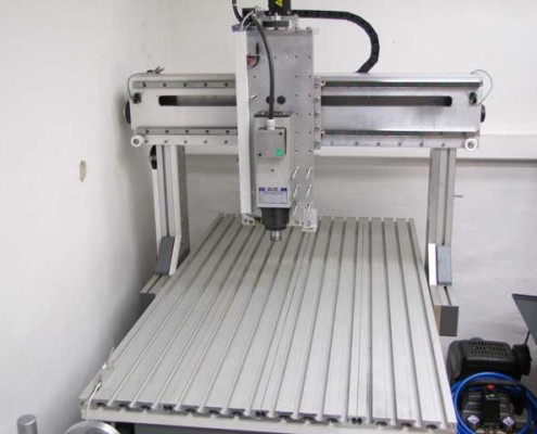
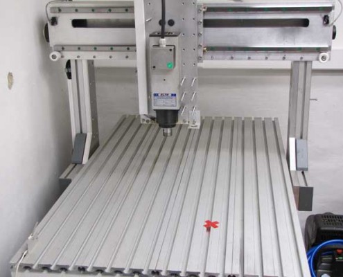
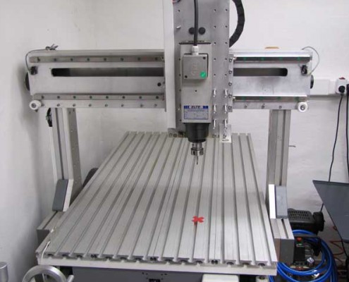
I will try to show you how to setup your CNC using PlanetCNC software. I will use my router machine as an example but you can do it similar way on all machine types. I use metric (millimeter) units but everything is same with imperial (inches) units except numbers are different (1mm is apporximately 0.03937in).
![1]()
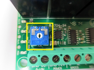
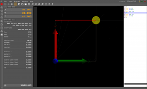
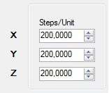
“Steps per unit” settings are already calculated and set. You should verify that distances in all directions are correct when machine moves. If position display changes for 100mm then machine should move 100mm.
If your SPU is not yet set please read SPU tutorial: How to set Steps Per Unit values?
First we need to set offsets to zero. Working offset should be set to zero with command “Machine/Offset/Zero”. “Empty” tool should be selected with with “Machine/Tools/Select/Empty” and tool offset should be set to zero with with “Machine/Tools/Zero Tool Offset” command. These commands will be explained later. For now it is important that everything is set to zero.
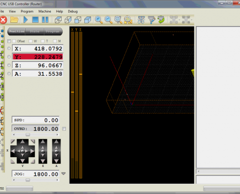
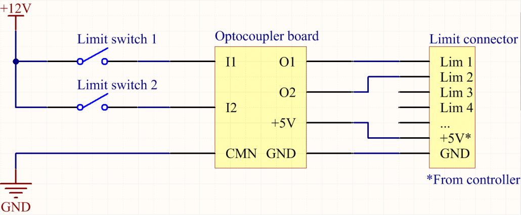
Limit switches
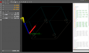
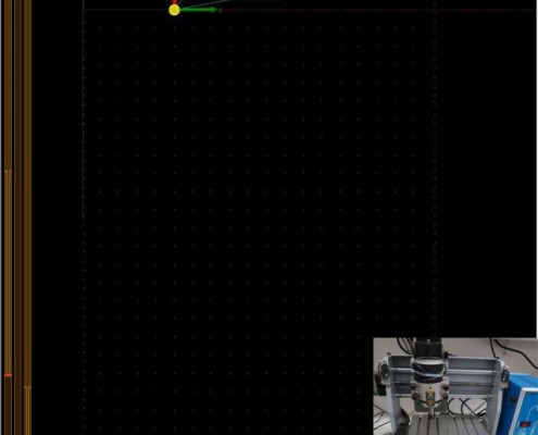
Machine that I will use has 5 limit switches. Two limit switches on X, two on Y and one on Z axis. To verify that all limit switches are working, trigger switch with hand and position display will become red or purple.
![2]()
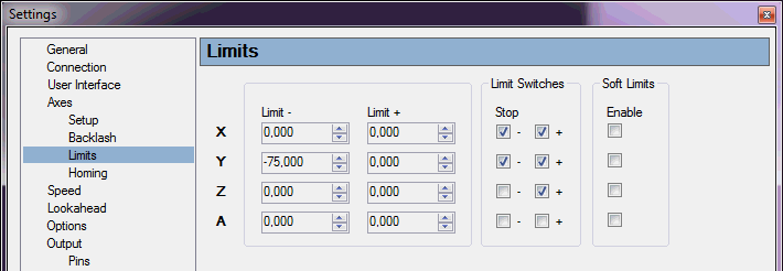
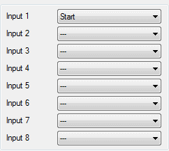
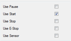
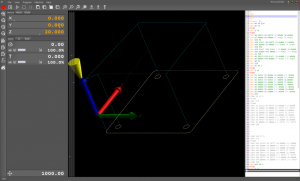
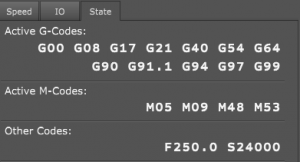
Triggered limit switch should stop machine. Machine should go to e-stop mode. To do this “Limit Switches Stop” checkboxes should be checked.
![3]()
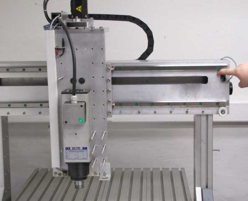
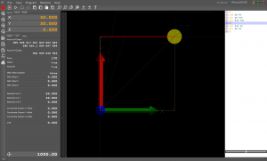
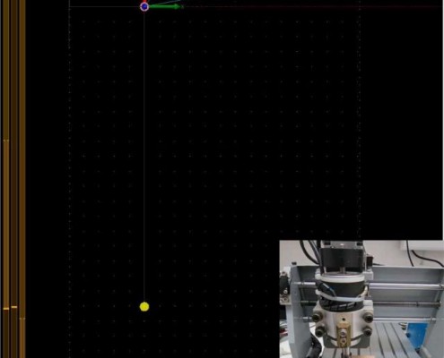
To verify that limit switches stop the machine, jog in direction of limit switch and trigger it with hand. Machine should stop. Be careful not to hurt yourself. Your hand near moving machine in usually not good idea so keep safe distance.
![4]()
When machine stops you should be able to jog in opposite direction. All 5 limit switches should be verified like this.
Limit switches can be used as reference switches. This means that we will use them to set machine absolute coordinates. This is known as homing.
Homing
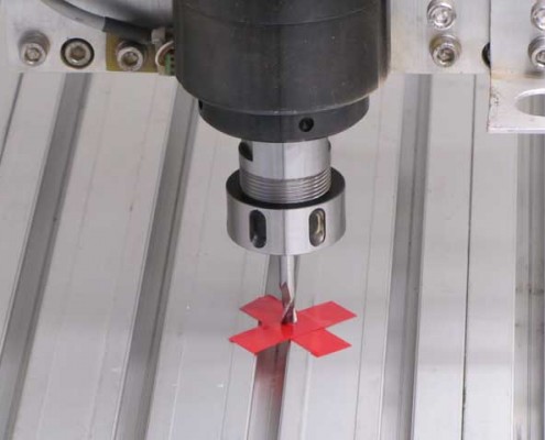
We need to choose where machine absolute zero position is. Usually machine works in relative coordinates and it is not really important where absolute zero is. What is important is, that it is always at same position. I will put some tape to mark it so that you will see it better on image.
![5]()
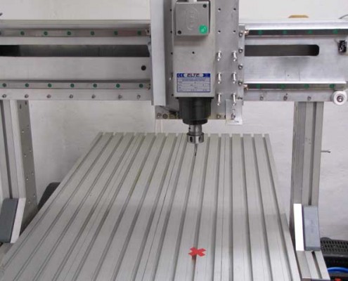
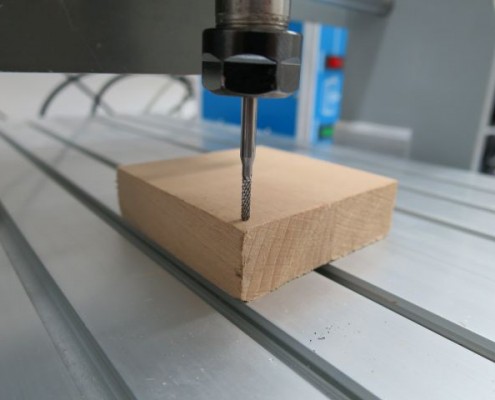
Tool is put in spindle and machine is jogged to this position. Be careful not to crush tool into machine table when you descent Z axis. You can just loosely tighten tool in spindle and if accident happens nothing will be damaged.
![6]()
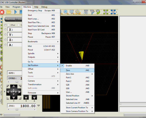
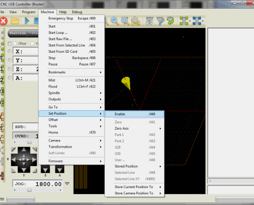
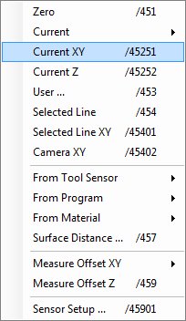
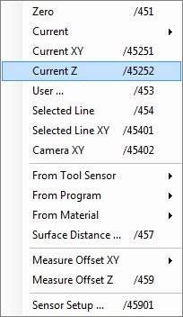
This position should be machine absolute zero. Commands for changing machine absolute position are in menu “Machine/Set Position”. Because it is usually not good idea to change absolute position make sure that “Machine/Set Position/Enable” is checked to enable these commands. Later we will uncheck this to prevent unwanted absolute position change. Now we can execute “Machine/Set Position/Zero” command and set absolute position to zero.
![7]()
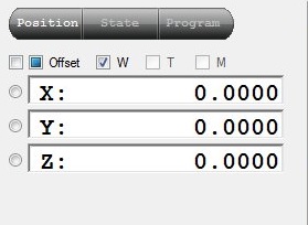
You will notice that position display now shows all zeros.
![8]()
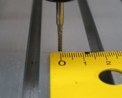
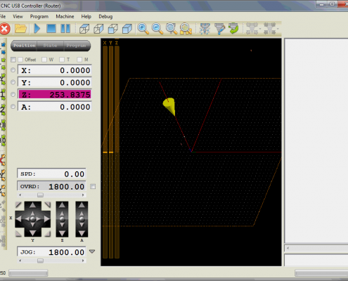
Slowly jog Z axis up until Z+ limit switch is hit and machine stops. Position display will be purple.
![9]()
![10]()
Write down Z position (253.8375mm in this case). Jog in opposite direction so that limit switch is released.
Repeat this for X axis.
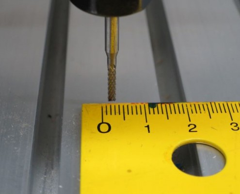
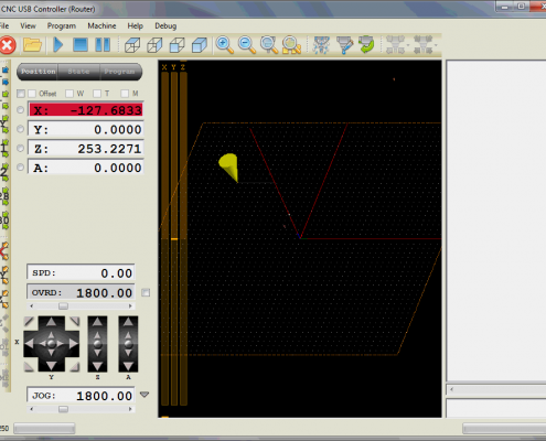
Slowly jog in X- direction until limit switch is hit and machine stops. Position display will be red.
![11]()
![12]()
Write down X position (-127.6833mm in this case). Jog in opposite direction so that limit switch is released.
And again for Y axis.
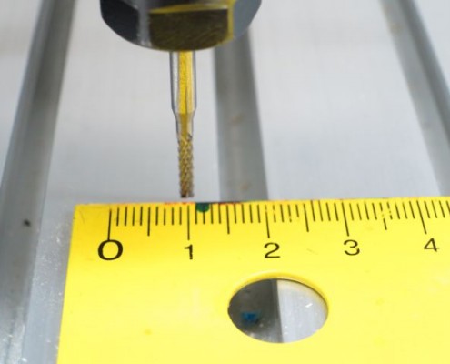
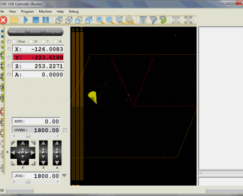
Slowly jog in Y- direction until limit switch is hit and machine stops. Position display will be red.
![13]()
![14]()
Write down Y position (-223.6188mm in this case). Jog in opposite direction so that limit switch is released.
We now have limit switch positions for all 3 axes and we can set homing.
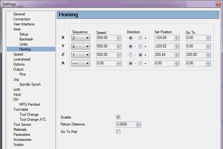
Open settings, section “Axes/Homing” and check “Enable”.
Usually we want to home Z axis first so we set “Sequence” for Z axis to be “1”. Then we will home X and Y at same time so we set “Sequence” for X and Y to be “2”.
When machine triggers limit switch during homing it stops in a moment. That is why we need to approach limit switch with slow speed. In this tutorial we will set “Speed” to 500mm/min but each machine is different and you should find what works on yours.
We used Z+, X- and Y- limit switches in this tutorial. This is set with “Direction” setting.
Perhaps you noticed that when switch is triggered you need to move back short distance to release it. Some switches need longer distance, some very small, but all switches need this. For switches on this machine 3mm is good value. This is set as “Return Distance”. Switch actually requires a lot less but this is good safe value. Don’t use 0!
For “Set Position” value we will use limit switch positions that we measured earlier. We will add/subtract 3mm that we used for “Return Distance”.
With “Go To” we set where we want machine to go after limit switch is hit. Machine will be at this position be after homing. Usually it is X0 Y0 and Z at some safe height. We know now that machine highest Z position is 250.84 (we measured this few steps back) so Z200 seems like a good value.
Normally machine first moves to all limit switches first and goes to “Go To” position at the end. If we want to change this order and move to final position as soon as axis triggers limit switch we can check “Go To First”. Some machines need this to avoid clamps. This machine does not need this.
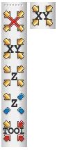
Here are all these settings:
![15]()
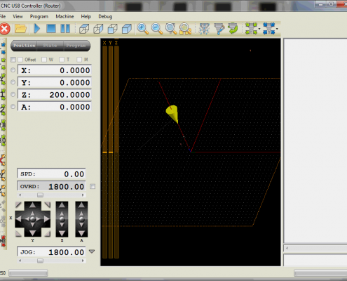
We can close settings and “Machine/Home” command will be enabled (if it is not then press E-stop twice to force display refresh).
We are ready to execute “Machine/Home” for first time. There is also button on toolbar for this. As always, be ready to hit e-stop is something goes wrong.
After homing machine is at X0 Y0 Z200. This is exactly 200mm over marking that we made.
![16]()
![17]()
Machine is homed and now we can use absolute coordinates. We can move machine anywhere we want and we will know exactly where it is. It is important not to change absolute position. We will uncheck “Machine/Set Position/Enable” now.
![18]()
If your machine losses steps for any reason you’ll need to do homing again.
Table size
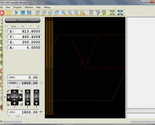
Now that we can move machine anywhere we want and we know exactly where it is we can use this to measure machine table. We will slowly jog machine to X+ and Y+ direction until limit switch is hit and then back a little so that switch is released. Write down position. It is X813.8000mm and Y460.4208mm.
![19]()
![20]()
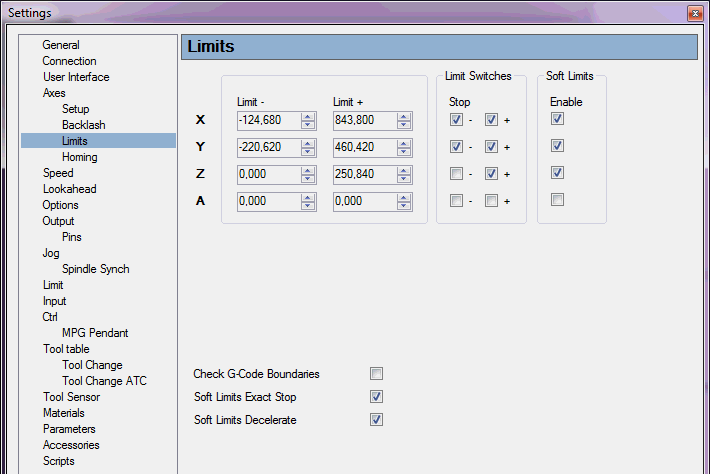
Table is measured and we will use this data to set machine limits and enable soft limits. Orange box on 3D display is now accurately representing machine working space.
![21]()
Soft limits
Soft limits are used to decelerate machine to stop before machine is stopped hard way at limit switch or before it crashes. I recommend “Soft Limits Decelerate” and “Soft Limits Strict” settings are also checked. Sometimes we need to disable soft limits and there is a command for this in menu “Machine/Soft Limits”. When soft limit is triggered position display will be yellow.
Measuring tool offset with fixed tool sensor
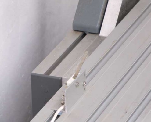
We can now set fixed tool sensor. Fixed tool sensor is usually used to measure tool length offset. We need to have machine homed so that we can use absolute positions. On machine used for this tutorial, fixed tool sensor is located in corner and connected to INPUT5 pin. In this tutorial I use switch with lever which is good for tutorial but should not be used on real machine. Switch lever is not horizontal and it will not give accurate results.
![22]()
First we will enable tool sensor in settings. This will enable sensor related menus and commands. Then we need to test if it works. Trigger sensor with hand. Word “Sensor” should appear on software status bar. Now we need to test if sensor stops machine. Jog machine away from sensor and to high Z position. Then slowly jog down and trigger fixed sensor with hand. Machine should stop.
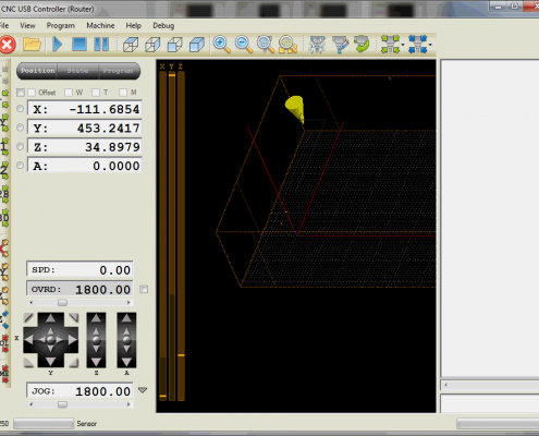
Jog machine so that tool is directly above sensor. Slowly jog down until tool triggers sensor and stops. Write down position. In this case it is X-111.6854mm, Y453.2417mm, Z34.8979mm.
![23]()
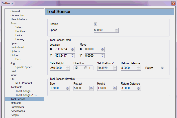
Open setting again, section “Tool Sensor”, group “Tool Sensor Fixed”. We set X and Y “Location” of our sensor. We could also set lead-in “Move” but for most machines this is zero. We need to set “Speed” which should be small because of momentary stop when tool triggers sensor. “Direction” is usually set to -. Because of long lever on my sensor switch “Return Distance” is quite large. I will set it to 5mm. We also have Z position of sensor and we can set “Set Position Z” value. Usually we want to move machine around at maximum possible Z height. This machine has Z+ limit is slightly above 250mm. 250mm will be good value for “Safe Height”. “Return” checkbox enables automatic return to position before tool length measurement.
![24]()
Now we can test if tool offset measuring with fixed tool sensor works.
Jog machine somewhere in the middle and execute “Machine/Tools/Measure Tool Offset”. There is also button on toolbar for this. As always when you do something for first time – be ready to hit e-stop.
If everything is correct machine should go rapidly up tu safe height, then traverse to fixed sensor location. Then it will descend at low speed until sensor is triggered. Machine will return back a distance to release sensor and use its Z position to calculate tool offset. Then it will rapidly move up to safe height, traverse back to original position and then move down until tip of your tool is at same Z height as it was before.
When tool offset is active small checkbox labeled “T”, just above position display, will be enabled. If this “T” checkbox is checked then position display will include tool offset.
It is important to get familiar with “Machine/Tools/Measure Tool Offset” command. See my video where I change tool length and it always returns to same position. Note how I’m doing this so that even if something goes wrong I still have time to press e-stop.
The post How to setup CNC machine using PlanetCNC software and controller? appeared first on Planet CNC.

 ,
,
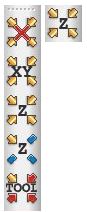
 . We want to move