One of the most important steps when setting up your machine in PlanetCNC TNG software is configuring machines max speed and acceleration values.
With speed and acceleration values that are not suitable for one’s machine, user risks lost steps(stepper motor) or increased torque(servo motor), damaged work-pieces, broken machine and most important, lost time.
To obtain machines max speed and acceleration values, user should put his machine trough various tests. This way user will learn motion capabilities and limitations of his CNC machine.
With machine max values correctly set, user can be rest assured that his machine will perform safely within its limitations, achieving best results.
Speed and acceleration settings
As same as we cannot achieve blistering accelerations and record high speeds with a family car, we also cannot expect miracles with small desktop CNC machine.
While the main limitation of a car is usually its engine and chassis, CNC machine’s rigidness and motion capabilities base on its axis motor drives, mechanics and frame.
Machine motion consists of single motor motion(single axis movements) and combined motor motion (combined axis movements – e.g. circular motion).
User would need to obtain max speed and acceleration values for both types of working conditions, single motor motion as also combined motor motion.
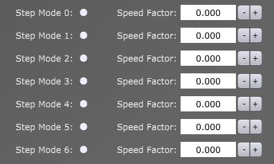
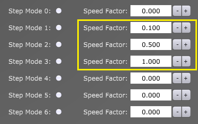
Single motor speed and acceleration settings are set under:
File/Settings/Motors/Speed & Acceleration:
![]()
![]()
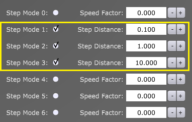
Combined motor speed and acceleration settings are set under:
File/Settings/Motion → Set Maximum Speed and Max Acceleration and Deceleration:
![]()
For standard 3 axis linear CNC machines, speed and acceleration values under Motors/Speed & Acceleration and Motion/ Speed & Acceleration are are usually the same.
Machine tests
Motion tests will help with approximation of suitable max speed and acceleration values of your machine. Like mentioned earlier, you would need to perform tests for both, single as also combined motor motion of X,Y and Z axes.
Z axis motion is little more specific than XY axis motion, since Z axis usually carries spindle motor which represents constant load on the Z axis motor. With motion such as hole array drilling and PCB hole drilling we can test Z axis motion capabilities.
It is recommended that some of these tests are performed also while machine is actually cutting/machining.
When machine cuts trough material, motors need to maintain speeds and accelerations while also dealing with resistance from material. Tests performed under these conditions can affect final max speed and acceleration values.
Single axis speed and acceleration test
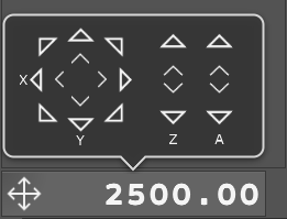
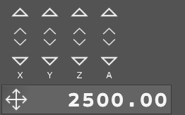
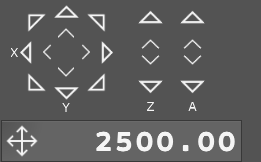
For this test you will move each axis independently in both directions. Start with default setting values, which are Speed = 2500 [mm/min] and Acceleration = 25[mm/s2].
You can start with X axis, then Y axis and as last Z axis.
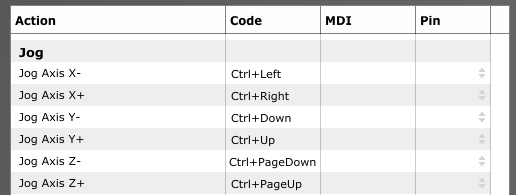
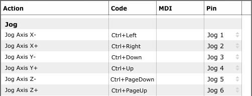
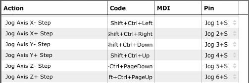
To move each axis you can use jogging keys or you can write short g-code program which would move each axis in desired distances and directions.
Trough out the test, configure Speed and Acceleration setting values depending on the given results of each test. If results indicate that axis could handle higher values, increase them, and if motor looses steps, lower these values. Please note that any unusual noises, vibrations, machine frame movements also indicate unsuited speed and acceleration values.
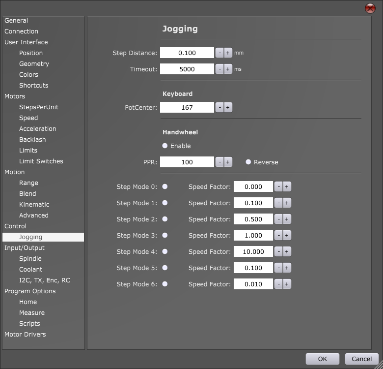
Hint: While acceleration values can be configured only via settings, you can set different speeds for testing by using JOG speed window. Double click on the value and insert new one.
Note that max jog speed is limited with max motor and motion speed values from settings.
Speed and Acceleration values that will be obtained with this test should be used for all further tests.
Combined axis speed and acceleration tests
Machine will use combined axis motion to perform these tests.
Rounded Square test
For this test you will use “Round Square” user defined feature. This UD feature generates toolpath program for square with round corners. Machine will perform round corners using combined axis motion, which is perfect for our test.
This test can be compared to a car cornering on a race track. If car gets thrown out of the track when passing trough corner, then it is safe to say that car speed was too high. If your machine will loose steps or motors will stall when traveling trough round corners, then set speed was too high.
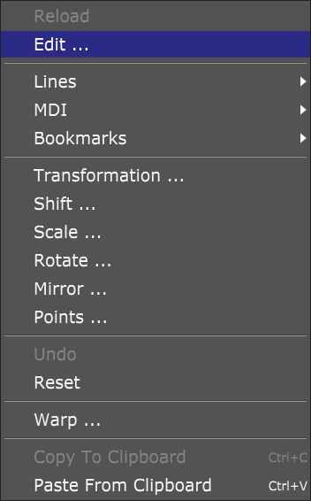
Under Machine/User Defined, locate Rounded Square option and start it:
![]()
Displayed dialog offers you to insert values for Size, Radius, Speed and Loop:
![]()
Size: Size of square sides. This value should be high enough so that machine can achieve max speed over each square side.
Radius: Equation offers you to calculate minimum radius that your machine will still be able to travel without lowering its speed, thus obtaining constant speed trough out the whole toolpath. Values for speed and acceleration (v and a) are those that we obtained with single axis test.
Speed: Max speed, speed value obtained with single axis speed and acceleration test.
Loop: Number of times machine will execute this square toolpath. Multiple executions of this toolpath program back to back can help with better observation of machine motion.
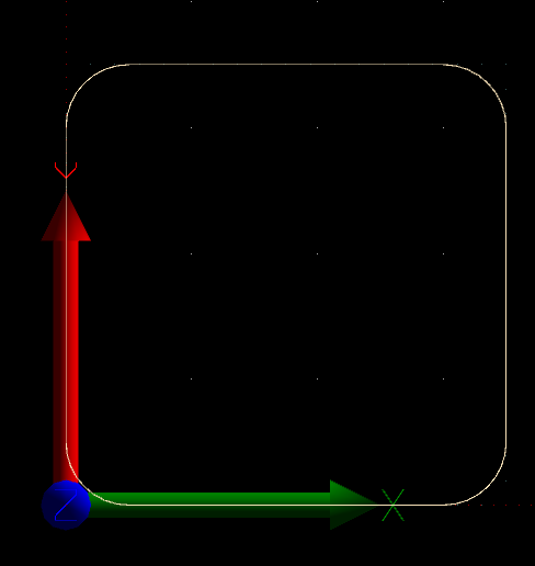
![]()
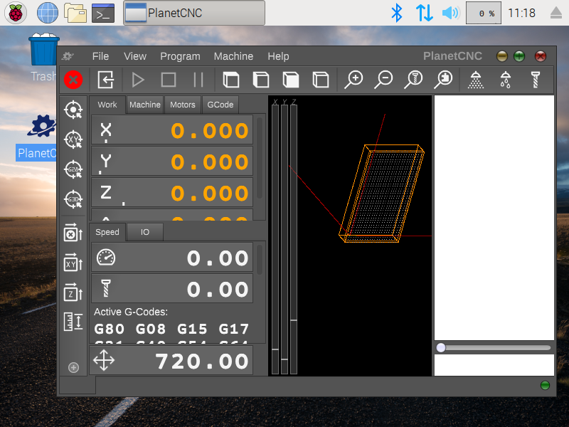
Click OK to start execution of square program and under speed dial observe if machine speed will change at any point:
![]()
If your machine performs this square toolpath with constant speed and without any problems, this indicates that your single axis max speed and acceleration values are suitable for your machine.
Mickey test
In PlanetCNC install folder locate Samples folder and open Mickey.nc file.
This g-code program uses motion which makes for a great test of combined axis motion.
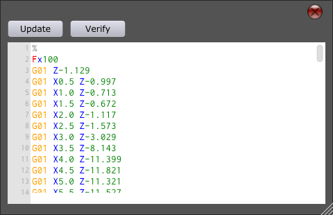
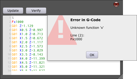
Since this program does not use F-word command it would be best to set it under File/Settings/Program Options → Feed Speed (Use max speed value obtained with single axis speed and acceleration test.)
![]()
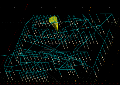
NC drill test
Hole array drilling and PCB drilling are great examples of Z axis motion where you can test your Z axis capabilities. Like mentioned earlier, Z axis motor needs to maintain position while also carrying spindle motors weight. With rapid and continuous Z axis motion, inertia can cause for Z axis motor to loose steps.
For this test, your machine should perform NC drill program file where machine drills lots of holes. Perform this test at max speed and acceleration values obtained with single axis speed and acceleration test.
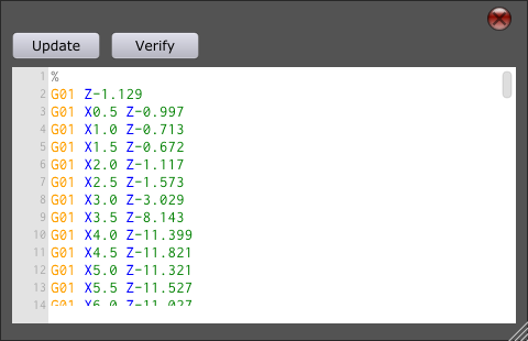
In PlanetCNC install folder locate Samples folder and open Mk1.ncd file.
For Feed Speed and Plunge Speed set max speed value obtained with single axis speed and acceleration test.
![]()
![]()
If lost steps or any other motion error occurs during these tests, you would need to lower max axis motor speed and acceleration values and repeat single axis speed and acceleration tests again. Then use new max values with combined axis speed and acceleration tests.
The post How to set speed and acceleration values in PlanetCNC TNG software appeared first on Planet CNC.